This post will detail some general best practices for VPLEX Back-end connectivity to an XtremIO storage array. As you will see from the diagrams below each VPLEX director should have redundant physical connectivity to the XtremIO storage array across Fabric-A & B. Due to the fact that XtremIO is an active/active array each X-Brick storage controller FC port has access to all provisioned storage on the array. In essence the objective here is to balance each VPLEX Director across each XtremIO Storage controller as evenly as possible thus avoiding any bottlenecks in connectivity between Back-end VPLEX to XtremIO front-end. The configuration examples provided (not limited to) are for the following scenarios:
◆ EXAMPLE 1: Single VPLEX Engine & Single XtremIO X-Brick
◆ EXAMPLE 2: Single VPLEX Engine & Dual XtremIO X-Brick
◆ EXAMPLE 3: Dual VPLEX Engine & Dual XtremIO X-Brick
◆ Further examples to follow…
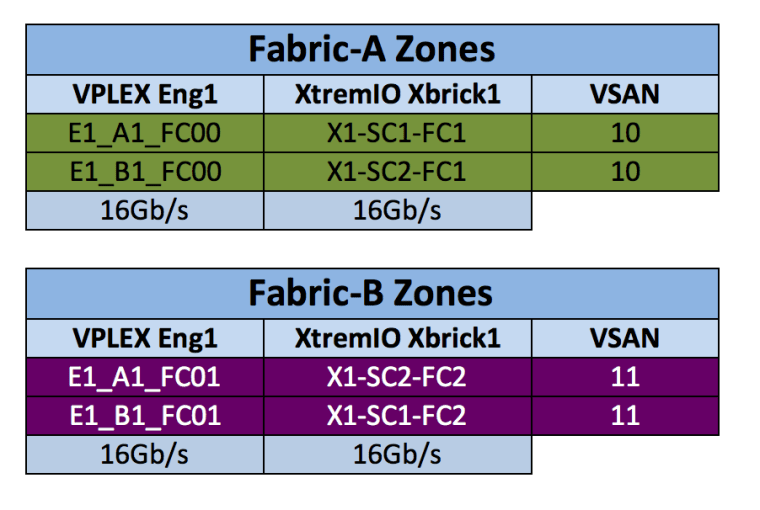
EXAMPLE 1: Single VPLEX Engine & XtremIO X-Brick
For this example the single engine VPLEX System has 50% of the available back-end ports connected: E1-A1-FC00, E1-A1-FC01, E1-B1-FC00, and E1-B1-FC01. This allows for a 1:1 mapping of VPLEX->XtremIO ports which equates to a total bandwidth of 32Gb/s between VPLEX->XtremIO. This design meets VPLEX HA requirements as each VPLEX director is zoned to both XtremIO SCs. The design also allows for future scalability of the XtremIO cluster as the remaining VPLEX back-end ports, E1-A1-FC02, E1-A1-FC03, E1-B1-FC02, and E1-B1-FC03 can be used to upgrade to a Dual X-Brick XtremIO configuration at a later stage (next example).

Cisco MDS-SERIES Zoning Configuration
The configuration steps below will detail creating:
◆ Alias’s for VPLEX Back-end & XtremIO Front-end ports
◆ Creating Zones
◆ Creating Zonesets
◆ Activate & Commit Zoneset
Example1: Download Zoning Configuration
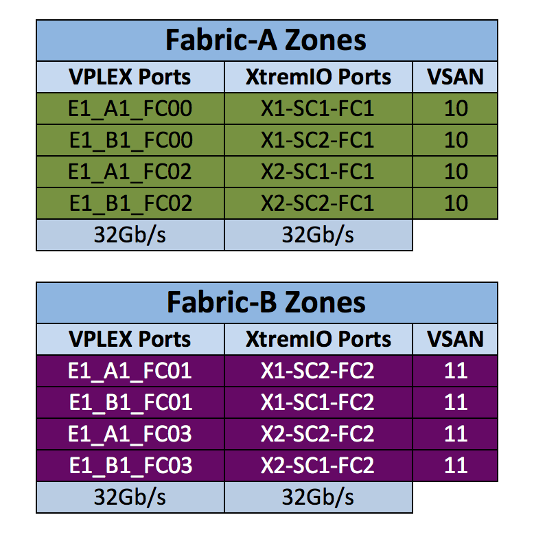
EXAMPLE 2: Single VPLEX Engine & Dual XtremIO X-Brick
For this example the single engine VPLEX System has 100% of the available back-end ports connected: E1-A1-FC00, E1-A1-FC01, A1-FC02, A1-FC03 and E1-B1-FC00, E1-B1-FC01, E1-B1-FC02, E1-B1-FC03. This again allows for a 1:1 mapping of VPLEX->XtremIO ports which equates to a total bandwidth of 64Gb/s between VPLEX->XtremIO. Each VPLEX director is zoned to all 4 XtremIO SCs for maximum HA and bandwidth:


Example2: Download Zoning Configuration
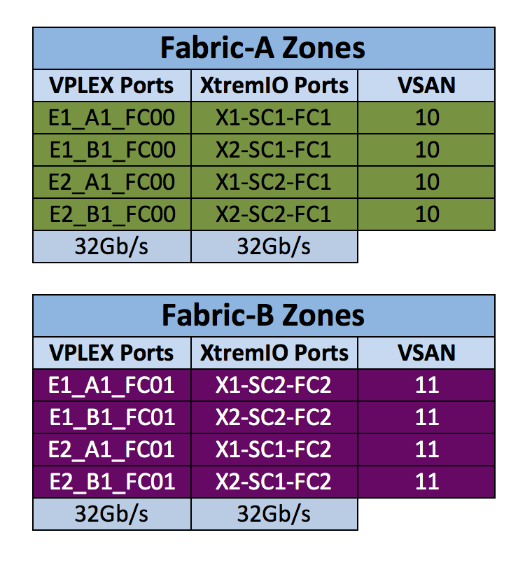
EXAMPLE 3: Dual VPLEX Engine & Dual XtremIO X-Brick
For this example the Dual engine VPLEX System has 50% of the available back-end ports connected: E1-A1-FC00, E1-A1-FC01, E2-A1-FC00, E2-A1-FC01, and E1-B1-FC00, E1-B1-FC01, E2-B1-FC00, E2-B1-FC01. This again follows a 1:1 mapping of VPLEX->XtremIO ports which equates to a total bandwidth of 64Gb/s between VPLEX->XtremIO. By using 50% of the available ports on each VPLEX director in a dual-dual configuration allows for a future expansion of the XtremIO cluster to a Quad configuration and still maintain a 1:1 mapping from a Dual VPLEX solution. Each VPLEX director is zoned to all 4 XtremIO SCs for maximum HA and bandwidth:


Example3: Download Zoning Configuration
XtremIO Initiator Groups
Each IG can access all of the created storage volumes within the array once the storage is mapped to the Initiator Group, there is no requirement as is the case with other arrays to configure groups of array ports/initiators/volumes such as masking views or storage groups, with XtremIO you simply create the IG and map the required volumes to that IG (see earlier post “Creating Initiator Groups and Mapping LUNs”)
Related XtremIO maximums v4.x:
◆ Maximum volumes per IG = 2048 (3.0.x the limit is 1024)
◆ Maximum volumes presented to VPLEX = 4096
◆ Maximum volumes per cluster = 8192
◆ Mapping limit for XtremIO is 16,384 volumes to Initiator Groups
In most cases a single XtremIO Initiator Group shall suffice for VPLEX->XtremIO connectivity due to the fact that you may present up to a maximum of 2048 volumes to a single IG, this equates to 2048 XtremIO system mappings (one volume map counts as one mapping). In the event that greater than 2048 volumes are required you may group all the back-end ports of VPLEX into 2 XtremIO Initiator Groups and map them to the volumes as follows: configure VPLEX Back-end ports FC00 and FC01 across all directors to one IG and ports FC02 and FC03 across all directors to a second IG, essentially this type of configuration would allow a VPLEX cluster to be seen as 2 independent hosts from the XtremIO cluster allowing the user to theoretically provision the maximum allowed 4096 volumes from one XtremIO cluster to one VPLEX cluster! At a high level this is an example configuration:
Initiator Group1: assign ports FC00 and FC01 across all directors to one IG. Map VPLEX Volumes 1-2048 to IG1 = 2048 Mappings
Initiator Group2: assign ports FC02 and FC03 across all directors to a second IG. Map VPLEX Volumes 2049-4096 to IG2 = 2048 Mappings
At this stage we now have 4096 Mappings and 4096 Volumes presented to VPLEX with 50% of volumes mapped to 50% of VPLEX BE ports FC00 and FC01 and the remaining 50% of volumes mapped to ports FC02 and FC03.
The above example allows to scale to the maximum limit of 4096 volumes but if there is no requirement to scale beyond 2048 volumes then a single XtremIO IG may contain all 32 VPLEX BE ports.
This recommended best practice configuration would apply to any combination of XtremIO X-Bricks to VPLEX Engines.
Note (VPLEX aside): Mappings per cluster = 16,384. The only way we would ever reach the maximum of 16,384 mapping is if volumes were shared across multiple initiator groups. Example maximum mapping configuration:
2048volumes assigned to IG1 & IG2 = 4096 mappings
2048volumes assigned to IG3 & IG4 = 4096 mappings
2048volumes assigned to IG5 & IG6 = 4096 mappings
2048volumes assigned to IG7 & IG8 = 4096 mappings
TOTAL = 8192volumes / 16,384 mappings
ViPR
While the following examples provide the associated Cisco zoning for their respective configurations, in the case where ViPR is part of the solution you may chose to either manually complete this task as per the example scripts below which is seamless to ViPR or let ViPR automatically handle this zoning configuration task. As an example if you chose to allow ViPR to automatically configure the Back-end zoning and you only require at the time to use 50% of the available VPLEX BE ports (depending on the VPLEX-XtremIO config and future scalability requirements) then you can manually tell ViPR to use only the FC00 & FC01 director ports, ViPR follows VPlex-XtremIO best practices and chooses ports based on maximum redundancy.
Where the number of X-Bricks is less than the number of VPLEX Engines ViPR will automatically zone 2 Paths Per VPlex Director allowing the flexibility to scale the number of X-Bricks as outlined in the examples below.
Another point to note is ViPR at present in the case of a VPLEX-XtremIO solution recognises only a single XtremIO IG thus a 2048 volume limit applies when using ViPR.
Useful References:
EMC® VPLEX SAN Connectivity Implementation Planning and Best Practices:
Click to access h13546-vplex-san-connectivity-best-practices.pdf


Regarding EXAMPLE 3: Dual VPLEX Engine & Dual XtremIO X-Brick, what is the impact if we used the four back end port of each director ?