Storage
VMAX VG2/8 – Masking View & Cisco Zoning Script
This post will cover the Masking and Zoning scripts for a VG when using Cisco MDS fabric switches. This post will not cover the creation or rules around the Control […]
Virtualization & Storage

This post will cover the Masking and Zoning scripts for a VG when using Cisco MDS fabric switches. This post will not cover the creation or rules around the Control […]
This post will cover the Masking and Zoning scripts for a VG when using Cisco MDS fabric switches. This post will not cover the creation or rules around the Control volumes, please reference the latest EMC publications for guidelines around quantity and size of the control volumes. The following example configuration applies to ‘VNX File OE 7.1’.
Note: Please reference EMC documentation for precise instructions as this is an example only config for deploying a ‘VNX VG’ with a VMAX.
The following is a list of the celerra control volumes and sizes required for the NAS installation:
• 2 x 12394 cylinders (11.62 GB)
• 3 x 2216 cylinders (2.03 GB)
• 1 x 69912 cylinders (64 GB)
• 1 x 2 cylinder volume for the gatekeeper device
VG Control Volumes and their respective HLU ID’s:
• The two ‘11.62 GB’ control LUNs map to HLU 0 and 1.
• The three ‘2.03 GB’ control LUNs map to HLU 2, 3, and 4.
• The ’64 GB’ control LUN maps to HLU 5.
• 1 x ‘2 cyl’ gatekeeper LUN maps to 0F.
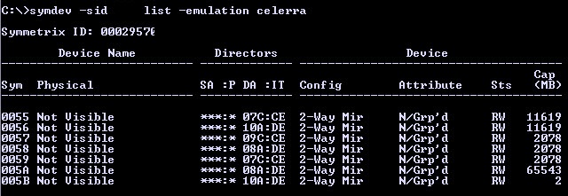
Listing the Control Volumes in order to gather their HEX values:
symdev -sid XXX list -emulation celerra
Add -v for a more detailed report:
symdev list -emulation celerra -v
In this example configuration we are using the F:1 ports on Engines 4&5:
#### List the Celerra LUN/ACLX MAPPING TO F1 FA ports: ####
symcfg -sid xxx -dir 7f -p 1 list -addr -avail
symcfg -sid xxx -dir 8f -p 1 list -addr -avail
symcfg -sid xxx -dir 9f -p 1 list -addr -avail
symcfg -sid xxx -dir 10f -p 1 list -addr -avail
1. MASKING VIEW CONFIG
Create the initiator group:
symaccess -sid XXX -name VG_IG -type initiator create -consistent_lun
If you have identified the Xblade WWPN’s from the fabric switches then you may add now, else you can wait until they are displayed by the Control Station during the NAS install:
symaccess -sid XXX -name VG_IG -type initiator -wwn 50060160…… add
symaccess -sid XXX -name VG_IG -type initiator -wwn 50060160…… add
symaccess -sid XXX -name VG_IG -type initiator -wwn 50060160…… add
symaccess -sid XXX -name VG_IG -type initiator -wwn 50060160…… add
Create the port group using the VMAX FA Ports 7f:1,8f:1,9f:1,10f:1:
symaccess -sid XXX -name VG_PG -type port create
symaccess -sid XXX -name VG_PG -type port -dirport 7f:1,8f:1,9f:1,10f:1 add
Note: Ensure the ACLX volume is mapped to these FA ports 7f:1,8f:1,9f:1,10f:1 as 0E.
symdev -sid XXX list -aclx -v provides detailed information for the ACLX volume.
See here for further ACLX details: EMC VMAX – Access Control Logix (ACLX) Gatekeeper Mapping
Create the Storage Group:
Add the Control Devices as listed above (Do not add the gatekeeper volume at this stage to the SG).
symaccess -sid XXX -name VG_SG -type storage create
symaccess -sid XXX -name VG_SG -type storage add devs 0055-005A
Create Masking View:
symaccess -sid XXX create view -name VG_MV -sg VG_SG -pg VG_PG -ig VG_IG -celerra
symaccess -sid XXX show view VG_MV
Now add 1 x 2 cyl Gatekeeper with a HLU value of 0F:
symaccess -sid XXX -name VG_SG -type storage add devs 005B -lun 0f -celerra
Verify the configuration:
symaccess -sid XXX show view VG_MV
symaccess -sid XXX list logins
2. Cisco MDS Zoning
It is good practice to isolate the file traffic on its own dedicated VSAN. In this example VSAN’s 20-Fabric-‘A’ and 21-Fabric-‘B’ are used specifically for the NAS traffic between the VG & VMAX. Traditional single initiator single target zones applied using standard cisco sequence: Create facalias | Create Zone | Add Members to Zone | Create Zoneset | Add Zones to Zoneset | Activate Zoneset | Save Config.
This example uses pWWN for the FCALIAS (you can also use FCID or fabric port WWN (fWWN)).
Fabric A Zoning
## Collect Interface details: ##
show interface description | grep VMAX40K
fc2/15 VMAX40K_7f1
fc3/19 VMAX40K_9f1
show interface description | grep XBlade
fc1/17 XBlade 2-00/00
fc4/29 XBlade 3-00/00
## VMAX WWNs: ##
show flogi database interface fc 2/15
7f1: 50:00:09:75:00:xx:xx:59
show flogi database interface fc 3/19
9f1: 50:00:09:75:00:xx:xx:61
## XBLADE WWNs: ##
show flogi database interface fc 1/17
XBlade 2: 50:06:01:60:xx:xx:xx:xx
show flogi database interface fc 4/29
XBlade 3: 50:06:01:68:xx:xx:xx:xx
## Configure: ##
conf t
interface fc2/15, fc3/19, fc1/17, fc4/29
no shut
vsan database
vsan 20 name NAS_WORKLOAD_VSAN_A
vsan 20 interface fc2/15, fc3/19, fc1/17, fc4/29
fcdomain domain 1 static vsan 20
fcdomain priority 2 vsan 20
fcdomain restart vsan 20
fcalias name XBlade2-00-00 vsan 20
member pwwn 50:06:01:60:xx:xx:xx:xx
fcalias name XBlade3-00-00 vsan 20
member pwwn 50:06:01:68:xx:xx:xx:xx
fcalias name VMAX40K_7f1 vsan 20
member pwwn 50:00:09:75:00:xx:xx:59
fcalias name VMAX40K_9f1 vsan 20
member pwwn 50:00:09:75:00:xx:xx:61
zone name XBlade2-00-00_to_VMAX-7f-1 vsan 20
member fcalias VMAX40K_7f1
member fcalias XBlade2-00-00
zone name XBlade3-00-00_to_VMAX-9f-1 vsan 20
member fcalias XBlade3-00-00
member fcalias VMAX40K_9f1
zoneset name zs_vsan20 vsan 20
zone name XBlade2-00-00_to_VMAX-7f-1
zone name XBlade3-00-00_to_VMAX-9f-1
zoneset activate name zs_vsan20 vsan 20
zone commit vsan 20
Copy Run Start
show zoneset active vsan 20
Fabric B Zoning
show interface description | grep VMAX40K
fc2/15 VMAX40K_10f1
fc3/19 VMAX40K_8f1
show interface description | grep XBlade
fc1/17 XBlade 2-00/00
fc4/29 XBlade 3-00/00
## VMAX WWNs: ##
show flogi database interface fc 2/15
10f1: 50:00:09:75:00:xx:xx:65
show flogi database interface fc 3/19
8f1: 50:00:09:75:00:xx:xx:5d
## XBLADE WWNs: ##
show flogi database interface fc 1/17
XBlade 2: 50:06:01:61:xx:xx:xx:xx
show flogi database interface fc 4/29
XBlade 3: 50:06:01:69:xx:xx:xx:xx
## Configure: ##
conf t
interface fc2/15, fc3/19, fc1/17, fc4/29
no shut
conf t
vsan database
vsan 21 name NAS_WORKLOAD_VSAN_B
vsan 21 interface fc2/15, fc3/19, fc1/17, fc4/29
fcdomain domain 2 static vsan 21
fcdomain priority 2 vsan 21
fcdomain restart vsan 21
fcalias name XBlade2-00-01 vsan 21
member pwwn 50:06:01:61:xx:xx:xx:xx
fcalias name XBlade3-00-01 vsan 21
member pwwn 50:06:01:69:xx:xx:xx:xx
fcalias name VMAX40K_10f1 vsan 21
member pwwn 50:00:09:75:00:xx:xx:65
fcalias name VMAX40K_8f1 vsan 21
member pwwn 50:00:09:75:00:xx:xx:5d
zone name XBlade2-00-01_to_VMAX-10f-1 vsan 21
member fcalias XBlade2-00-01
member fcalias VMAX40K_10f1
zone name XBlade3-00-01_to_VMAX-8f-1 vsan 21
member fcalias XBlade3-00-01
member fcalias VMAX40K_8f1
zoneset name zs_vsan21 vsan 21
zone name XBlade2-00-01_to_VMAX-10f-1
zone name XBlade3-00-01_to_VMAX-8f-1
zoneset activate name zs_vsan21 vsan 21
zone commit vsan 21
copy run start
show zoneset active vsan 21
NEXT: INSTALL NAS ON CONTROL STATION 0
====================================SUMMARY===================================
Congratulations!! Install for VNX software to release 7.1.76-4 succeeded.
Status: Success
Actual Time Spent: 40 minutes
Total Number of attempts: 1
Log File: /nas/log/install.7.1.76-4.Dec-02-11:54.log
=====================================END=======================================
3. Perform Checks
Verify NAS Services are running:
Login to the Control Station as ‘nasadmin’ and issue the cmd /nas/sbin/getreason from the CS console. The reason code output should be as follows (see detailed list of Reason Codes below):
10 - slot_0 primary control station

11 - slot_1 secondary control station

5 - slot_2 contacted

5 - slot_3 contacted
Check the status of the DATA Movers and view which slot is active:
nas_server -info -all
Confirm the VMAX is connected to the VG:
nas_storage -check -all
nas_storage -list
List detailed information of the config:
/nas/bin/nas_storage –info –all
Code Levels:
List the datamovers: nas_server -list
Check the DART code installed on the Data Movers: server_version ALL
Check the NAS code installed on the Control Station: nas_version
Network Configuration:
Control Station: /sbin/ifconfig (eth3 is the mgmt interface)
Data Movers: server_ifconfig server_2 -all
Date & Time:
Control Station: date
Data Movers: server_date ALL
List the disk table to ensure all of the Control Volumes have been presented to both Data Movers:
nas_disk -list
Check the File Systems:
df -h
Confirm the EMC NAS version installed and the model name:
/nasmcd/bin/nas_version
/nas/sbin/model
Check IP & DNS info on the CS:
nas_cs -info
Log Files:
Log file location: /var/log/messages
Example of NAS services starting successfully:
grep -A10 “Starting NAS services” /var/log/messages*
Output:
Dec 8 19:07:27 emcnas_i0 S95nas: Starting NAS services
Dec 8 19:07:46 emcnas_i0 EMCServer: nas_mcd: MCD will monitor CS IPMI connection.
Dec 8 19:08:46 emcnas_i0 EMCServer: nas_mcd: slot 0 missed 10 heartbeats from slot 1.
Dec 8 19:08:50 emcnas_i0 EMCServer: nas_mcd: Install Manager is running on slot 0, skipping slot 1 reboot
Dec 8 19:08:50 emcnas_i0 EMCServer: nas_mcd: Slot 0 becomes primary due to timeout
Dec 8 19:08:52 emcnas_i0 mcd_helper: All NBS devices are up
Dec 8 19:09:08 emcnas_i0 kernel: kjournald starting. Commit interval 5 seconds
Check the Data Mover Logs:
server_log server_2
Complete a Health Check:
/nas/bin/nas_checkup
Failing over a Control Station:
Failover:
/nas/sbin/./cs_standby -failover
Takeover:
/nasmcd/sbin/./cs_standby -takeover
Or reboot:
nas_cs –reboot
Determine the failover status of the Blades (Datamovers):
/nas/bin/nas_server -info –all
Initiate a manual failover of server_2 to the standby Datamover:
server_standby server_2 -activate mover
List the status of the Datamover’s:
nas_server -list
Review the information for server_2:
nas_server -info server_2
Shutdown Datamover (blade):
/nas/bin/server_cpu server_2 -halt now
Power on the Datamover (blade):
/nasmcd/sbin/t2reset pwron -s 2
Restore the original primary Datamover:
server_standby server_2 -restore mover
VG Shutdown:
Shutdown Control Stations and DATA Movers:
/nasmcd/sbin/nas_halt -f now
List of Reason Codes:
0 – Reset (or unknown state)
1 – DOS boot phase, BIOS check, boot sequence
2 – SIB POST failures (that is, hardware failures)
3 – DART is loaded on Data Mover, DOS boot and execution of boot.bat, boot.cfg.
4 – DART is ready on Data Mover, running, and MAC threads started.
5 – DART is in contact with Control Station box monitor.
6 – Control Station is ready, but is not running NAS service.
7 – DART is in panic state.
9 – DART reboot is pending or in halted state.
10 – Primary Control Station reason code
11 – Secondary Control Station reason code
13 – DART panicked and completed memory dump (single Data Mover configurations only, same as code 7, but done with dump)
14 – This reason code can be set for the Blade for any of the following:
• Data Mover enclosure-ID was not found at boot time
• Data Mover’s local network interface MAC address is different from MAC address in configuration file
• Data Mover’s serial number is different from serial number in configuration file
• Data Mover was PXE booted with install configuration
• SLIC IO Module configuration mismatch (Foxglove systems)
15 – Data Mover is flashing firmware. DART is flashing BIOS and/or POST firmware. Data Mover cannot be reset.
17 – Data Mover Hardware fault detected
18 – DM Memory Test Failure. BIOS detected memory error
19 – DM POST Test Failure. General POST error
20 – DM POST NVRAM test failure. Invalid NVRAM content error (checksum, WWN, etc.)
21 – DM POST invalid peer Data Mover type
22 – DM POST invalid Data Mover part number
23 – DM POST Fibre Channel test failure. Error in blade Fibre connection (controller, Fibre discovery, etc.)
24 – DM POST network test failure. Error in Ethernet controller
25 – DM T2NET Error. Unable to get blade reason code due to management switch problems.

