Each Engine has two Directors with each Director containing two Back-End Fibre Channel I/O Modules (Labeled MOD0 & MOD1). These modules (also known as DA’s – Disk Adapters) provide Fibre […]
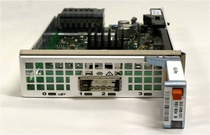
Each Engine has two Directors with each Director containing two Back-End Fibre Channel I/O Modules (Labeled MOD0 & MOD1). These modules (also known as DA’s – Disk Adapters) provide Fibre Channel Connectivity to the drives. As you can see from the image below there is just a single physical port on the Back-end IO Module, this single port is a Quad SFP port (QSFP). The connecting cable has a single copper QSFP transceiver connector consisting of 4 Fibre channel cables aggregated into one Single QSFP port. While at the Drive Bay side the 4 Fibre channel cables branch out as individual connections to the link control cards (LCC) as we will see shortly. Each DAE contains two LCC cards (LCCA & LCCB).
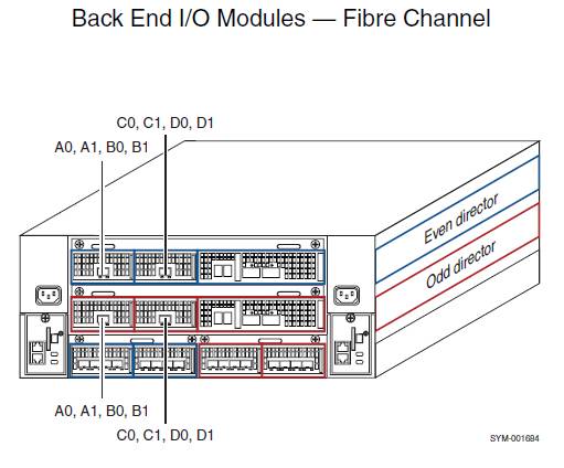
The Engine diagram below provides the Port layout on the Engine and as you can see the lower director is the odd director and the upper director is the even director. On both directors there are two Back-end IO modules (MOD0 & MOD1) per director, the Back End IO Module MOD0 has connections A0,A1,B0,B1 and MOD1 has connections C0,C1,D0,D1.
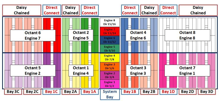
Here is an example of a Standard VMAX Storage Bay Configuration fully populated (8 Engines) with 10 storage BAYS as if viewed from the Front of the VMAX. In this fully populated configuration you have four direct connect storage bays (Bay 1’s) and six daisy chained Storage Bays (2’s & 3’s). Each octant represents connectivity from a Single Engine (2 x Directors).
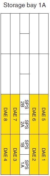
In order to keep this example simple I will focus on the First Engine in the VMAX which is Engine 4. Understanding how one engine connects to the backend will help to understand the remaining Back-end connectivity as the same rules apply. Below is ‘Disk Bay 1A’ (Rear) with DAE’s 1-8 populated, these are the DAE’s that Engine4 directly connects to:
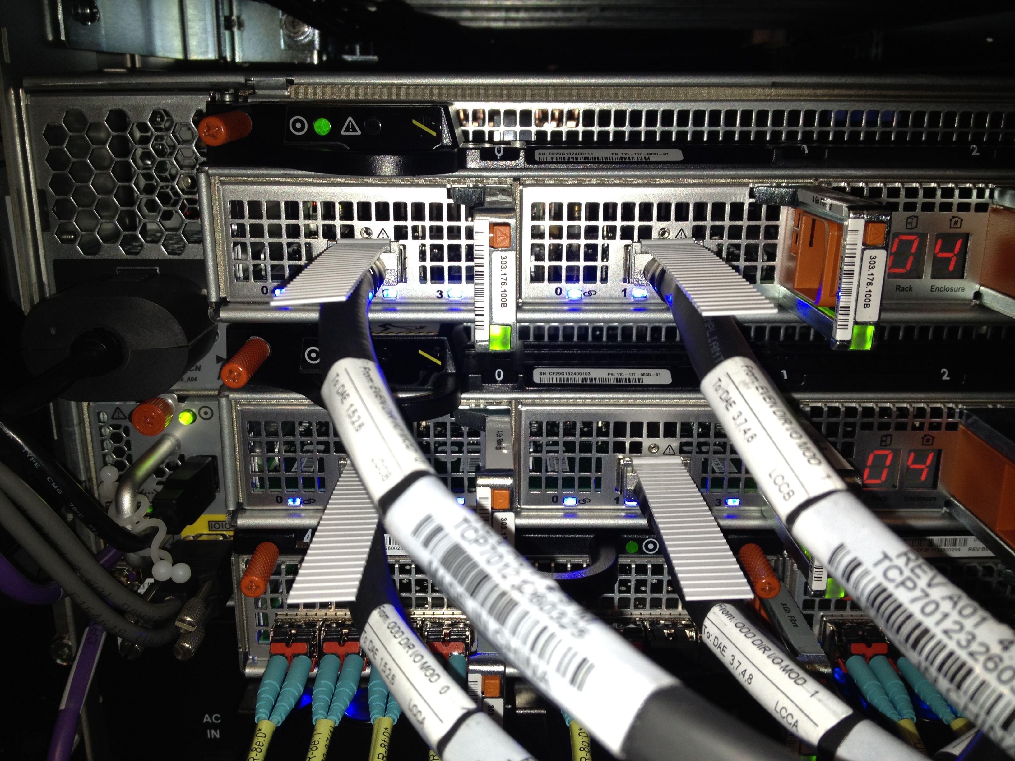
Engine 4 Backend IO Modules and QSFP Cables: Here are the four slics (MOD’s) on the Engine with each slic providing 4x4Gig FC links (Loops)
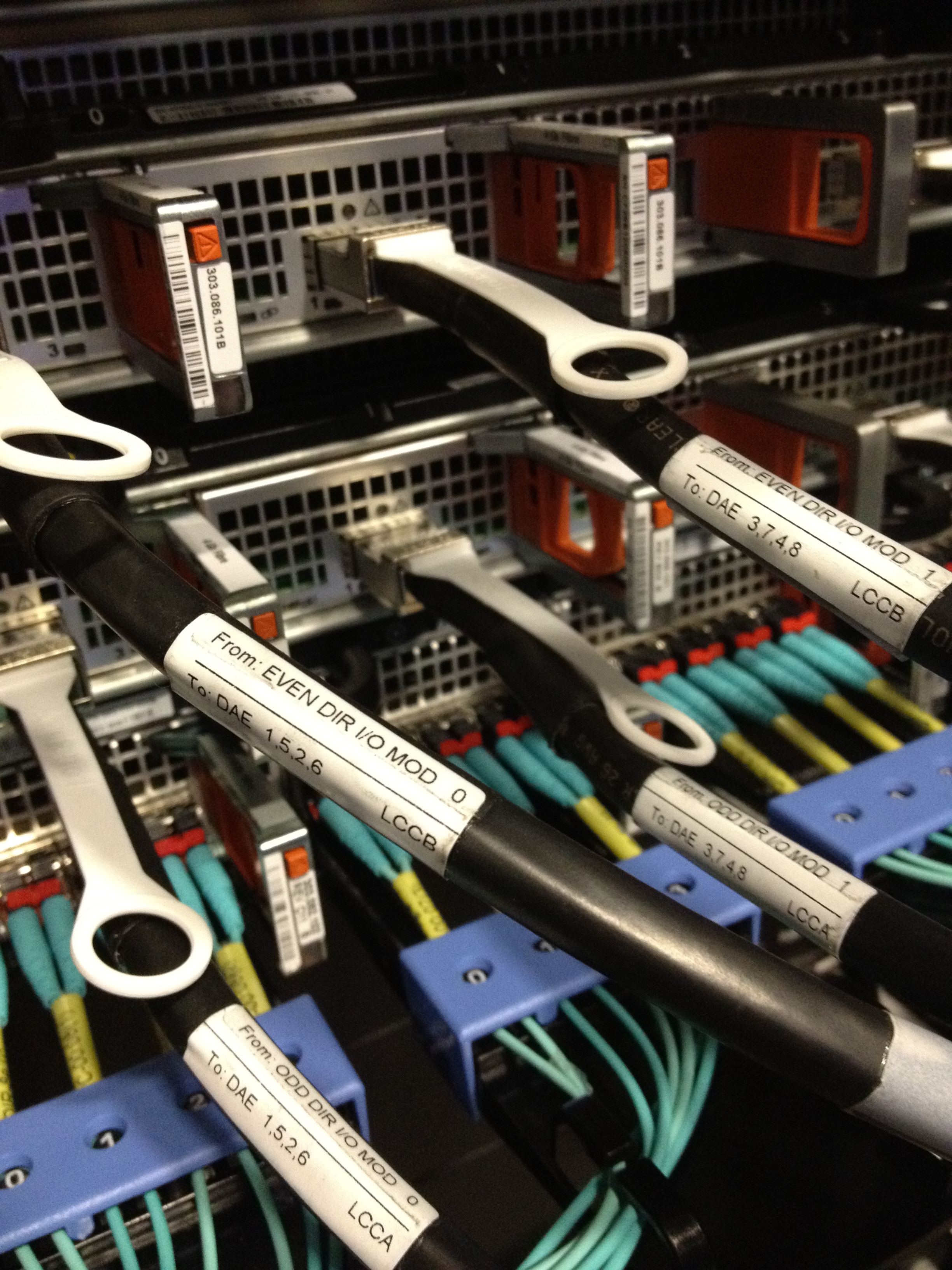
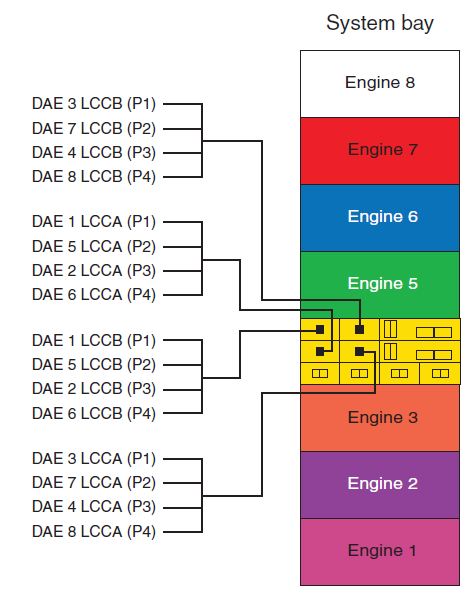
We can see from the labeling on the image below of Engine4 that the Even Director (DIR8) connects to LCCB and the Odd Director (DIR7) connects to LCCA. MOD0 on both the even and odd directors connect to DAE’s 1,5,2,6 with MOD1 on both directors connecting to DAE’s 3,7,4,8.
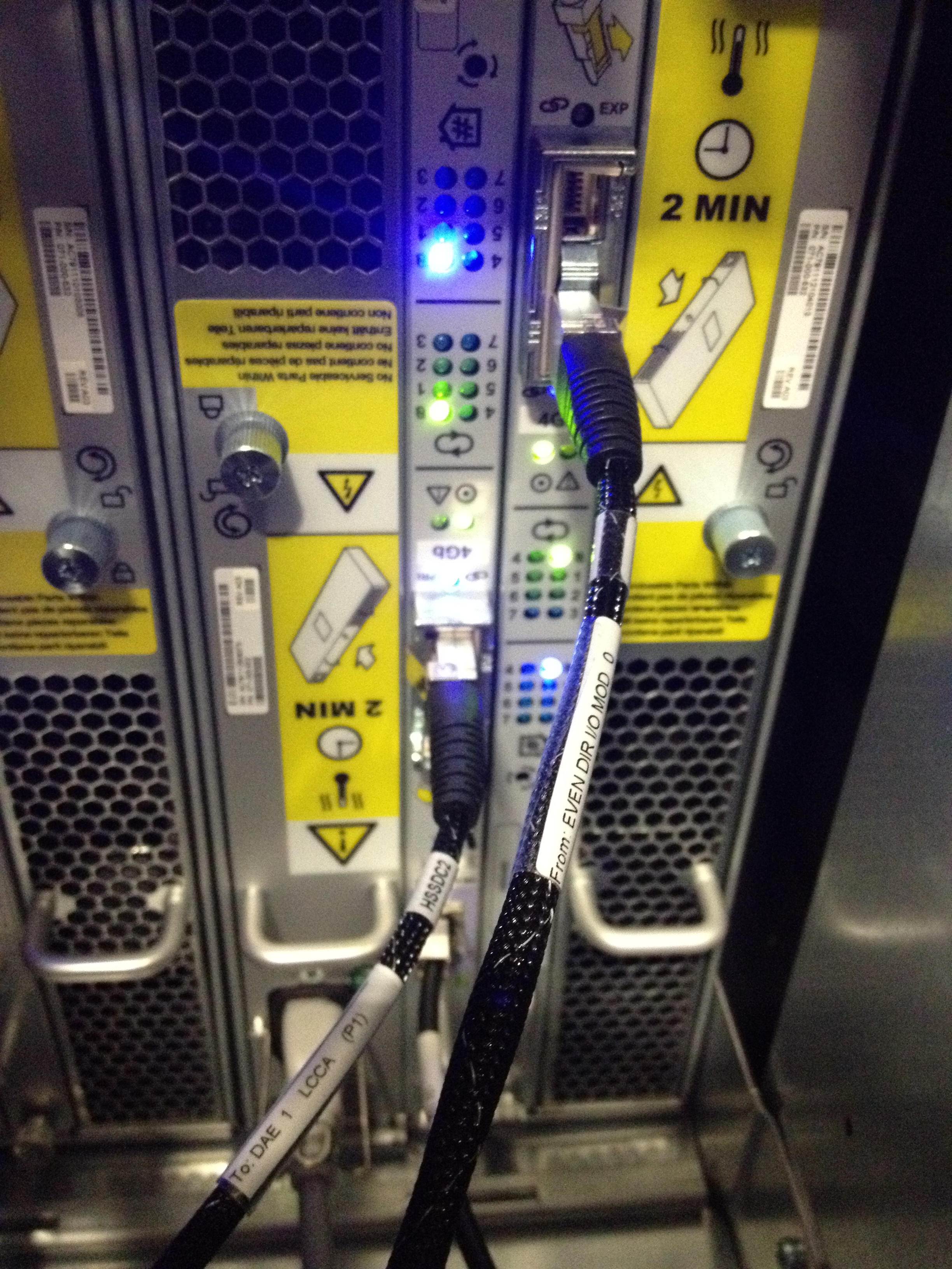
Checking the connectivity on DAE 1 you can see MOD0 from the Even Director (Dir8) connects to the primary port on LCCB and MOD0 from the Odd Director (Dir7) connects to the primary port on LCCA. Note that all connections from the Even Directors connect to LCCB and all the Odd directors connect to the LCCA cards. On the loop configuration you can see that DAE1 is on Loop0. There are 8 Redundant Loops in total from the Engine:
DAE1=LOOP0 (A0(P1))
DAE2=LOOP2 (B0(P3))
DAE3=LOOP4 (C0(P1))
DAE4=LOOP6 (D0(P3))
DAE5=LOOP1 (A1(P2))
DAE6=LOOP3 (B1(P4))
DAE7=LOOP5 (C1(P2))
DAE8=LOOP7 (D1(P4))
Here is the full connectivity map for Engine 4: Also note the following translations for MOD0 A0=P1 A1=P2 B0=P3 B1=P4 and likewise for MOD1 C0=P1 C1=P2 D0=P3 D1=P4
This completes the example of the direct attach Back-end cabling for Engine 4. The same rules apply as you add more engines. As a result of this design the back-end cabling provides dual access across directors to each drive eliminating any single point of failure (8 Redundant Loops).
To Summarize:
• 8 Redundant Loops – A0,A1,B0,B1,C0,C1,D0,D1
• LCCA Connects to the ODD number Director
• LCCB Connects to the EVEN number Director
• Each Engine supports a seperate octant
• Each Slic (MOD) has 4x4Gig FC Links (16 Backend FC Links Per Engine)
Note: Please reference EMC Documentation for more detailed information specific to your configuration. Depending on Engine counts and Direct/Daisy configurations your cabling may expand differently.
Hi Dave,
this article gives very good insight even for someone who doesn’t touch the systems day by day 🙂
I’m wondering how SAS is being realized in a Vmax. Are there SAS BE disk direcors available or is FC being converted to SAS in the LCC or DAE?
Thanks
Dieter
thank you for sharing this .. it helped me a lot 🙂
Hi Dave
This is very informative.
Can you post a similar post on the Front End Directors ? With pictorials representation ?
That will help in understanding the numbering of the FA ports per engine.
Really Awesome, Really thanks for sharing this information.
Kindly allow me to clear my doubts regarding this, If Engine 4 goes completely offline then will other engine get access to Engine 4 associated DAE’s. If yes then How they will get it.
Thanks 🙂
Roop
There are 2 directors per engine, if one fails you still have access to the spindles. Entire engine fails then you will not have access to the physical spindles connected that engine DA’s. Thanks
Good one Dave. Nicely explained.
Do you have a similar article posted for Vmax 3 architecture?


Hi Dave,
this article gives very good insight even for someone who doesn’t touch the systems day by day 🙂
I’m wondering how SAS is being realized in a Vmax. Are there SAS BE disk direcors available or is FC being converted to SAS in the LCC or DAE?
Thanks
Dieter
thank you for sharing this .. it helped me a lot 🙂
Hi Dave
This is very informative.
Can you post a similar post on the Front End Directors ? With pictorials representation ?
That will help in understanding the numbering of the FA ports per engine.
Thanks in advance
RN
Excellent DOC
Hi David
This Documents & informations are very useful.
Can u share some more DAE connectivity breif….
Thanks in advance
Hi Dav,
Greeting of the day 🙂
Really Awesome, Really thanks for sharing this information.
Kindly allow me to clear my doubts regarding this, If Engine 4 goes completely offline then will other engine get access to Engine 4 associated DAE’s. If yes then How they will get it.
Thanks 🙂
Roop
There are 2 directors per engine, if one fails you still have access to the spindles. Entire engine fails then you will not have access to the physical spindles connected that engine DA’s. Thanks
Good one Dave. Nicely explained.
Do you have a similar article posted for Vmax 3 architecture?